ENGINEERING AT AUGUSTA FIBERGLASS
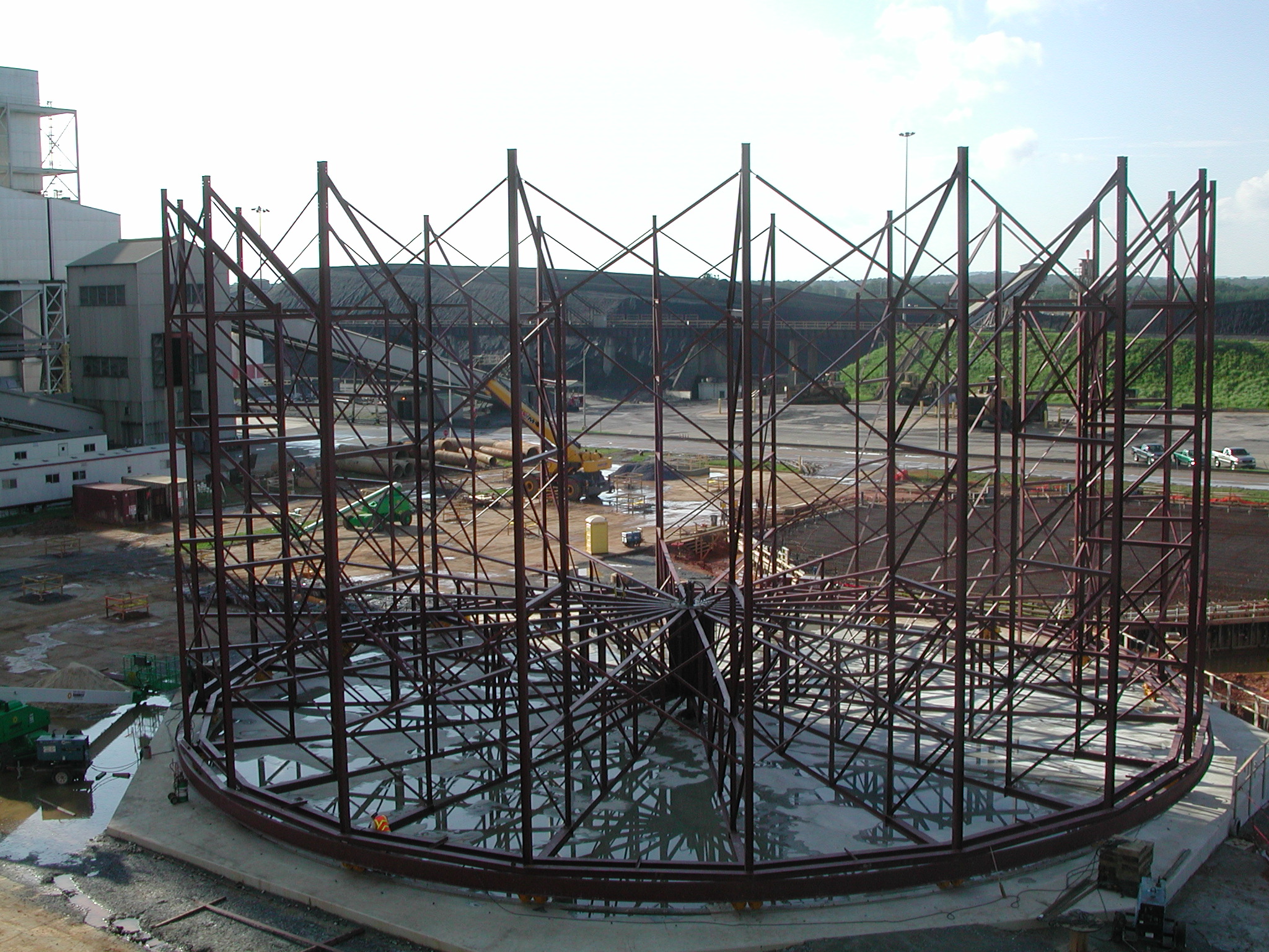
The Augusta Fiberglass Engineering team has decades of experience in Fiberglass Reinforced Plastics. Professional Engineers capable of performing Finite Element Analysis bring the best of engineering to each task. The vessels they have designed include the largest, most complex in the world. And, in order to meet the needs of its customers, the Augusta Fiberglass engineering team has designed and built highly complex winding and fabrication equipment including that needed to build 7 of the largest fiberglass vessels in the world at the customers’ job-site. In the process, Augusta Fiberglass earned several US Patents.

AFC engineers have also designed and built more than 11 miles of power stack liners and they have solved numerous complex duct problems. All projects no matter how large or how small are engineer reviewed to ensure that the finished product will withstand the forces and challenges created by the service intended for that equipment.
Sample Finite Element Analysis Projects Completed By Augusta Fiberglass Engineers.
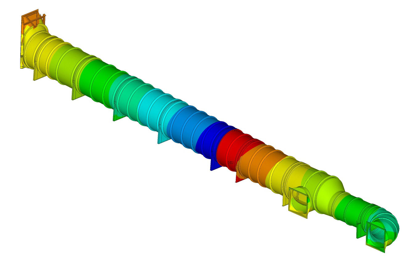
Duct with Elbow
This plot shows analysis of FRP duct with rectangular to round transitions,miter elbow, eccentric reducer, eccentric “Tee”, steel anchor and sliding saddle, turning vanes and eccentric round to rectangle transition. The duct, saddle, slide bearing were designed for the project specification and ASTM D5364. The stiffness of the steel support structure was taken into consideration by using spring elements. The global analysis checked the strains for each layer in each direction with the project allowable, buckling factor of safety for wind pressure and design external pressure, the stress and deflection in transition steel and FRP transition panel, saddle reactions, force at the duct joints and FRP flange deflection for the sizing of Expansion Joints. Local analysis was conducted to analyze steel anchor and sliding saddles, FRP joints, anchor shoulder, turning vanes, transition steel and slide bearing.
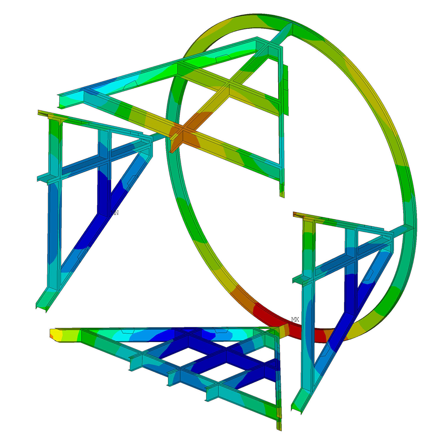
Steel Saddle
This plot shows the analysis of a steel saddle. The saddle reactions were obtained from the global analysis of the duct for various loads conditions. The saddle was analyzed for the load combinations listed in ASCE 7-10.
Turning Vane
This plot shows the analysis of FRP turning Vane. The boundary conditions from the global analysis were applied to the edges of the turning vane. The FRP panel and stiffener were designed to ensure that the deflections and stresses were below the allowable limits.
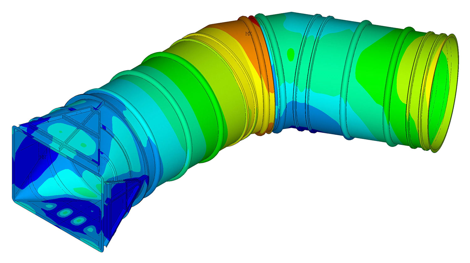
FRP Duct with Transition
This plot shows analysis of the FRP duct with elbow and eccentric rectangular to round transition. The duct and transition steel were designed for the project specification and ASTM D5364.
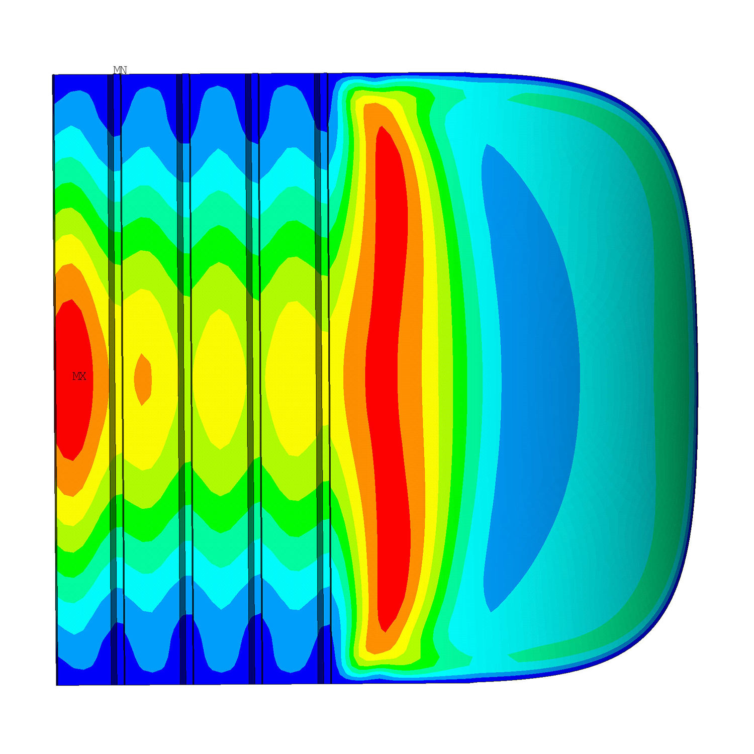
Transition Steel
This plot shows analysis of the FRP duct transition steel. The steel is designed to ensure both the deflection and stresses are below the allowable limits.
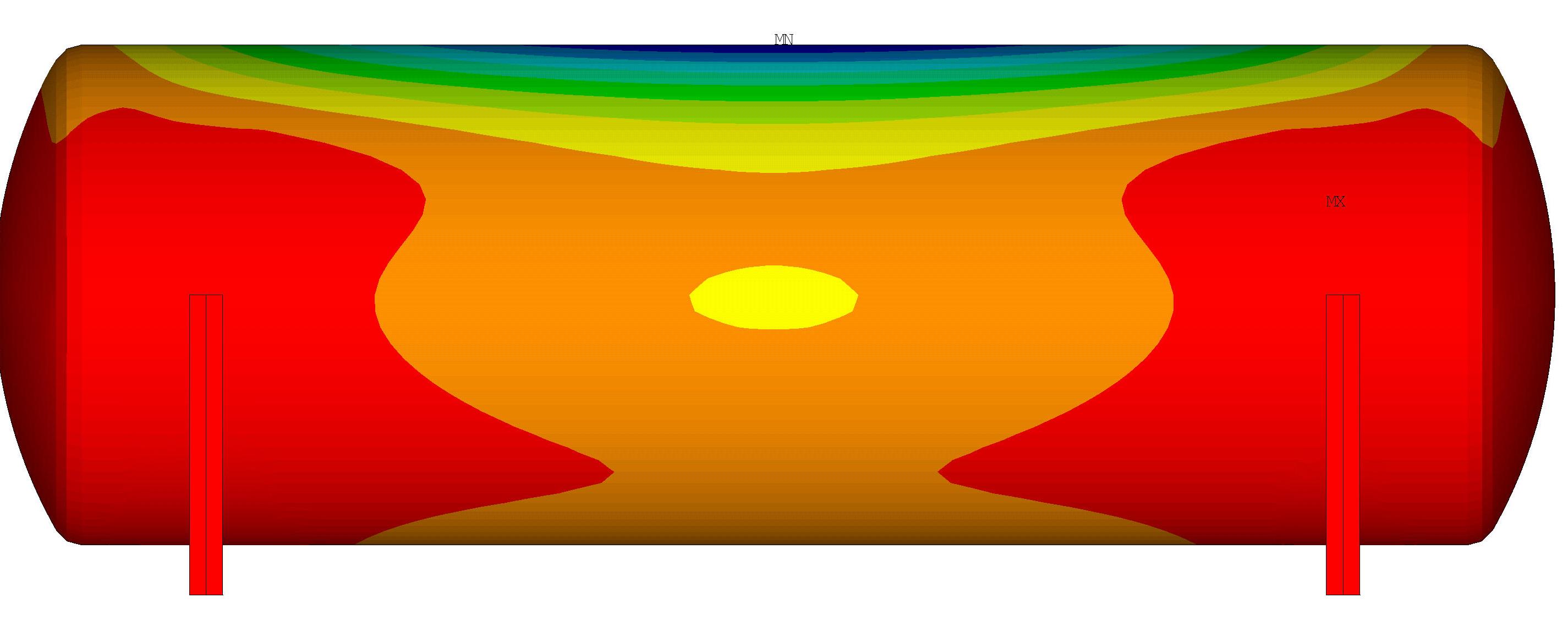
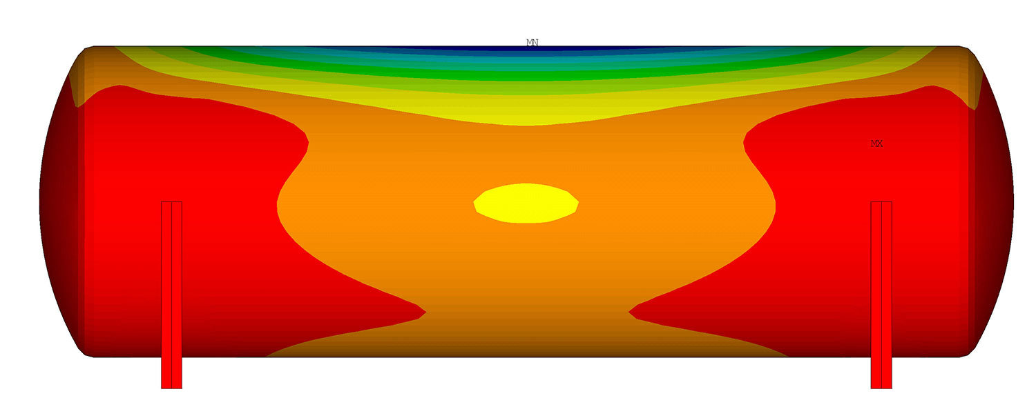
Horizontal Tank
This plot shows the design of a horizontal tank on steel saddle. A special subroutine was developed to apply the hydrostatic pressure of the tank contents. The tank is designed per ASME RTP-1 and the steel saddle per the load combinations listed in ASCE 7-10.
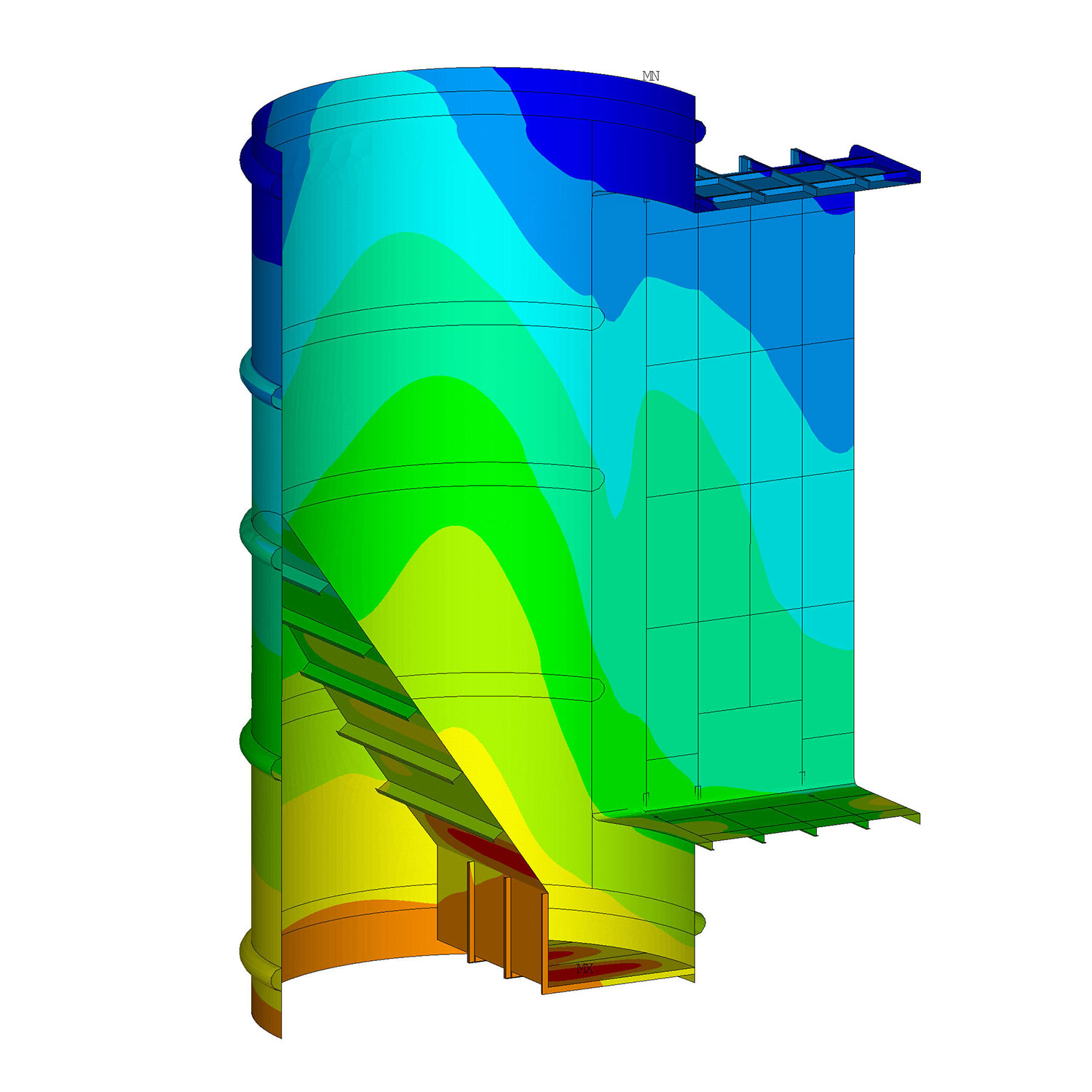
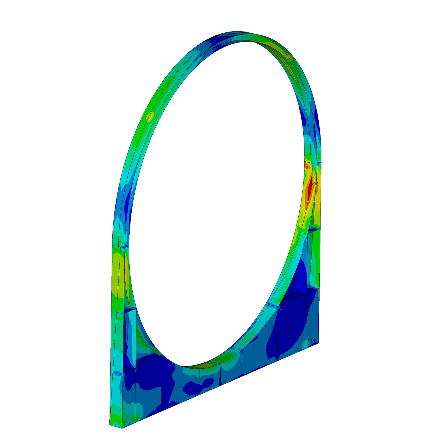
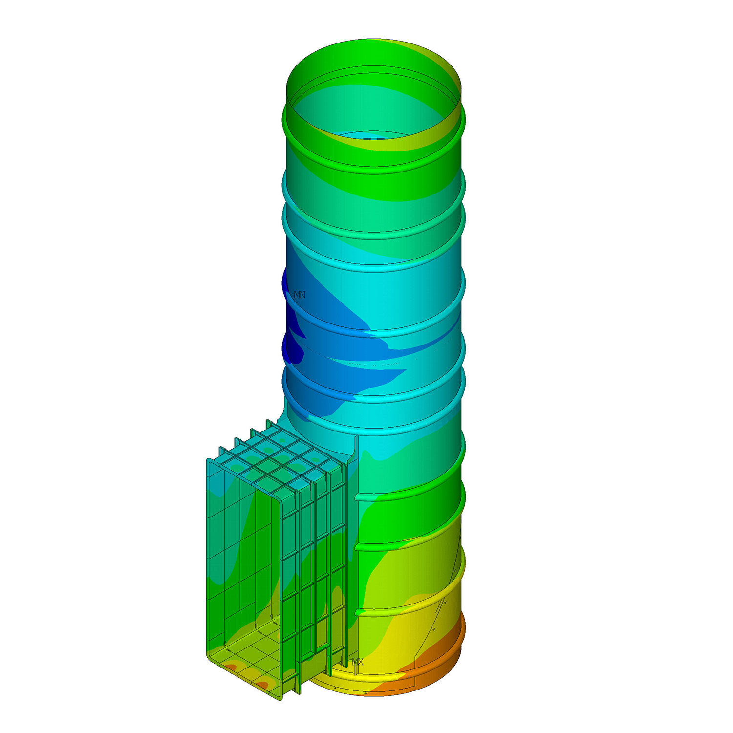
FRP Liner with Breach
This plot shows the analysis of a FRP liner inside a concrete chimney. The rotations and deflections of the chimney support are applied to the FRP liner support ring. The rectangular breach and stack liner bottom are reinforced by steel stiffeners. The FRP liner was analyzed for the load combinations per ASTM D5364.
FRP Liner Breach Detail
This is a half model of the liner and the breach shows the detail of the liner bottom, sump and breach steel.